Test models
Ribasim developers use the following models in their testbench and in order to test new features.
Code
import ribasim_testmodels
import matplotlib.pyplot as plt
from IPython.display import Markdown, display

for model_name, model_constructor in ribasim_testmodels.constructors.items():
    if model_name.startswith("invalid"):
        continue

    display(Markdown(f"\n# {model_name}\n"))
    if model_constructor.__doc__ is not None:
        display(Markdown(model_constructor.__doc__))

    model = model_constructor()
    fig, ax = plt.subplots(figsize=(6, 4))
    model.plot(ax)
    ax.axis("off")
    plt.show()
    plt.close(fig)
1 allocation_control
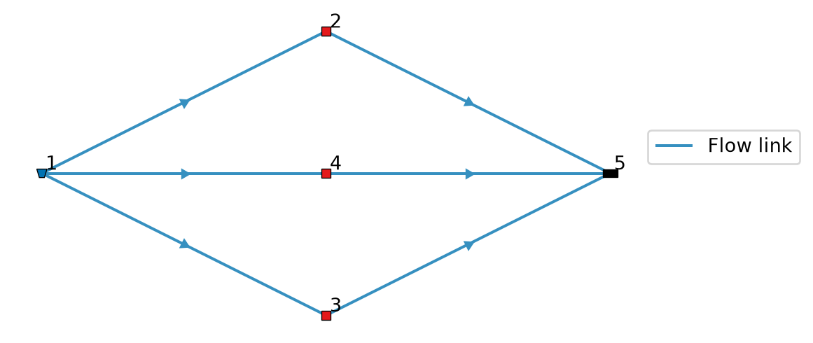
Create a model that has a pump controlled by allocation. 
2 allocation_example
Generate a model that is used as an example of allocation in the docs. 
3 allocation_off_flow_demand
Set up a model with a Pump with a FlowDemand but allocation turned off. 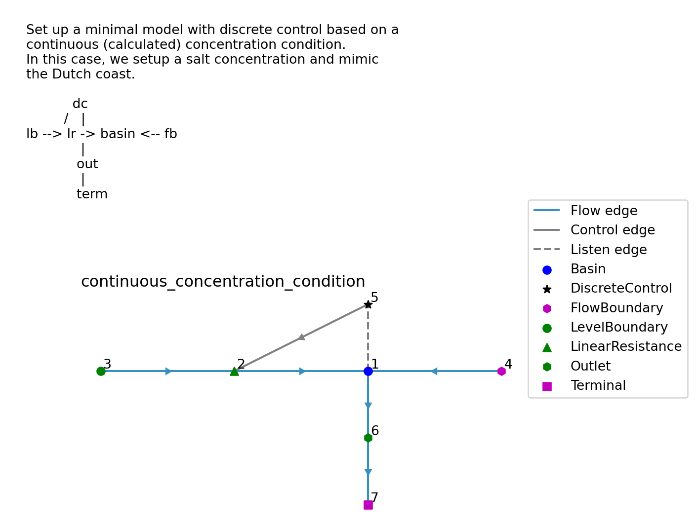
4 allocation_training
5 backwater
Backwater curve as an integration test for ManningResistance. 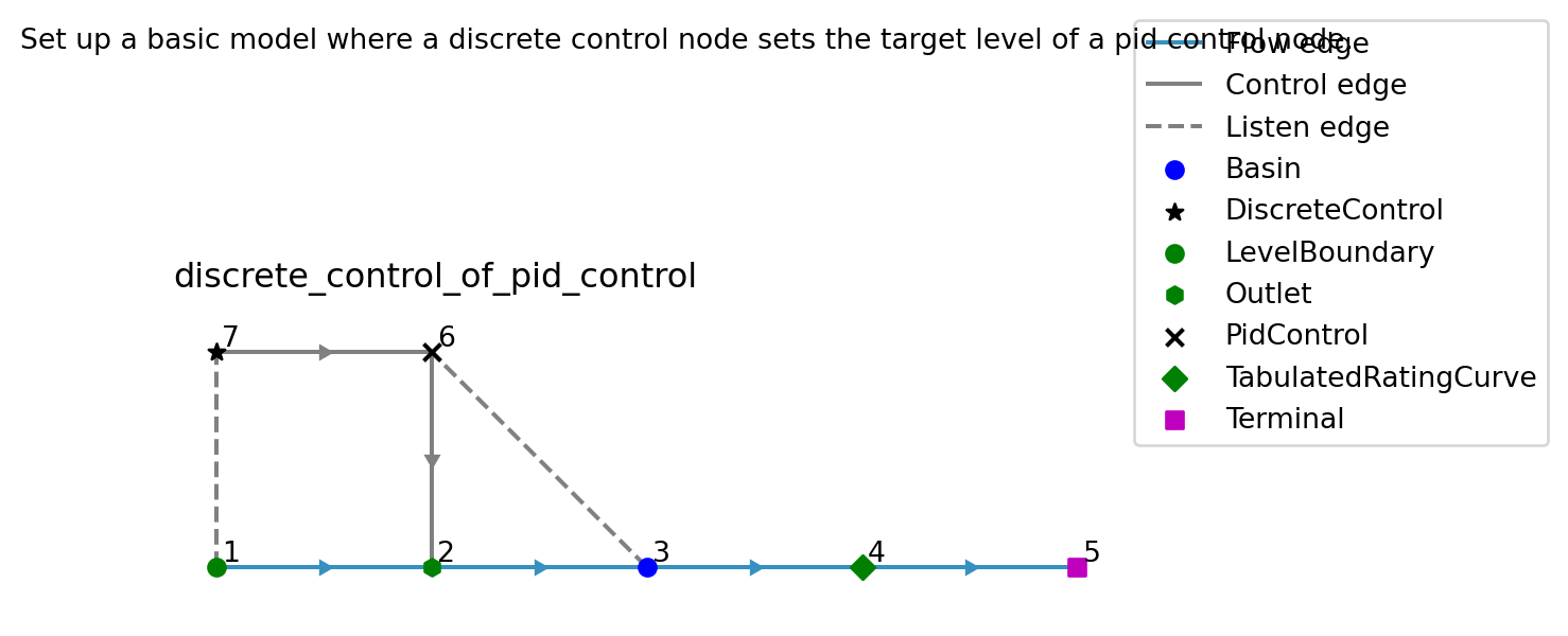
6 basic_basin_both_area_and_storage
7 basic_basin_only_area
8 basic_basin_only_storage
9 basic
10 basic_transient
Update the basic model with transient forcing. 
11 basin_overflow
Test model for basin overflow handling in allocation. 
12 bucket
Bucket model with just a single basin at Deltares’ headquarter. 
13 circular_flow
Create a model with a circular flow and a discrete control on a pump. 
14 compound_variable_condition
Model with a condition on a compound variable for DiscreteControl. 
15 concentration_condition
DiscreteControl based on a concentration condition. 
16 connector_node_flow_condition
DiscreteControl with a condition on the flow through a connector node. 
17 continuous_concentration_condition
DiscreteControl based on a continuous (calculated) concentration condition.
In this case, we setup a salt concentration and mimic the Dutch coast.
       dc
     /   |
lb –> lr -> basin <– fb | out | term

18 cyclic_demand
Create a model that has cyclic User- Flow- and LevelDemand. 
19 cyclic_time

20 demand_priority_default
Model with allocation where the UserDemand and FlowDemand omit the demand priority.
The demand priority is optional and defaults to 1. The LevelDemand gets priority 2, since flow and storage demands cannot share a priority.

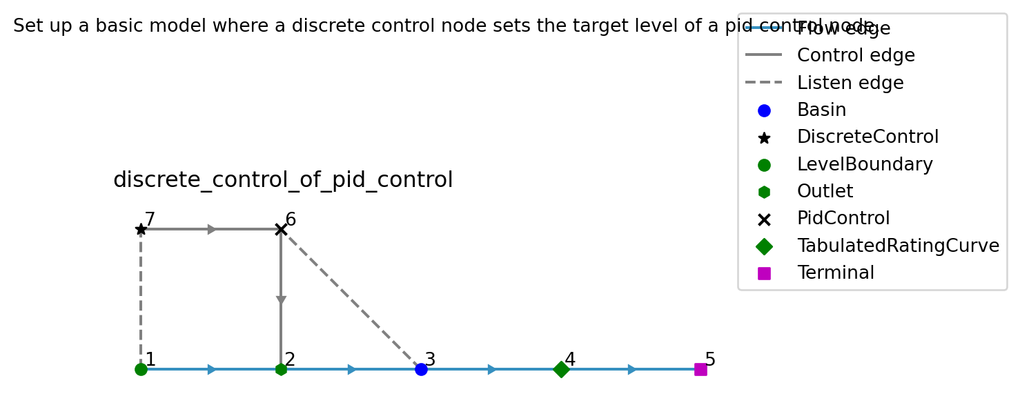
21 discrete_control_of_pid_control
Set up a basic model where a discrete control node sets the target level of a pid control node. 
22 drain_surplus
Set up a model which activates an outlet to drain surplus water out of a Basin. 
23 drought
Create a small subsection of the LHM Vechtstromen model containing a basin that runs dry (#2189). 
24 fair_distribution
See the behavior of allocation with few restrictions within the graph. 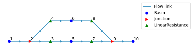
25 flow_boundary_interpolation

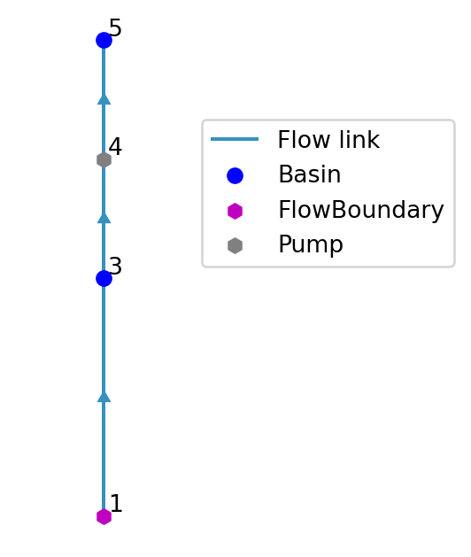
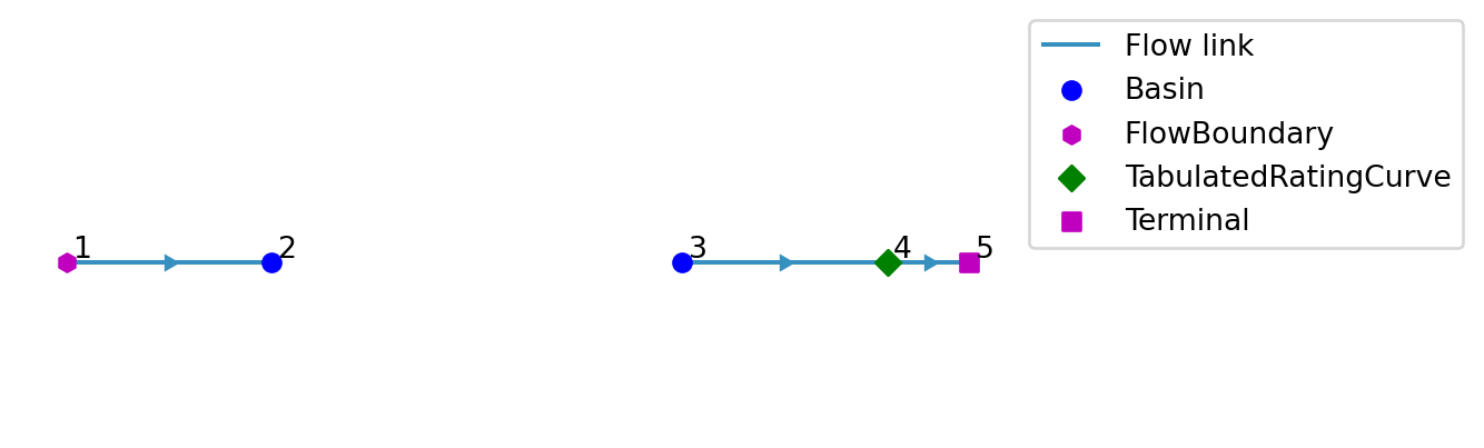
26 flow_boundary_terminal
Create a model with a FlowBoundary that flows straight into a Terminal.
Basin #3 only has an outflow via Pump #4, which is off, so it must not change.

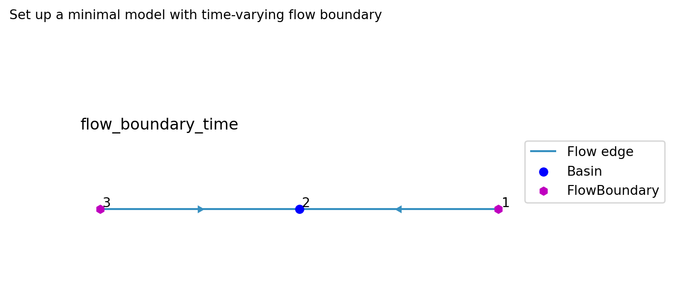
27 flow_boundary_time
Set up a minimal model with time-varying flow boundary. 
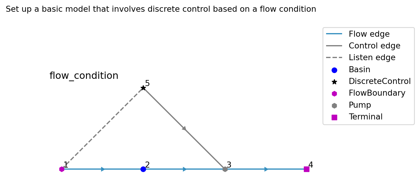
28 flow_condition
Set up a basic model that involves discrete control based on a flow condition. 
29 flow_demand_discrete_control
Set up a model with a Pump that has both a FlowDemand and a DiscreteControl.
The DiscreteControl switches the Pump between allocation control and a prescribed flow rate, based on the level of the upstream Basin.

30 flow_demand
Small model with a FlowDemand. 
31 junction_allocation
Create a model for testing allocation with Junction nodes that divide the flow.
A FlowBoundary (3e-3 m³/s) and a Pump (2e-3 m³/s) flow into Junction #4. UserDemand #5 abstracts its demand of 4e-3 m³/s first, and the remaining 1e-3 m³/s is divided over Basin #8 (70%) and Basin #9 (30%). The return flow of the UserDemand (50%) flows via Junction #10, which stays in the simulation, into Basin #11.

32 junction_allocation_shortage
Create the Junction allocation model with a demand above the 5e-3 m³/s inflow.
UserDemand #5 asks for 8e-3 m³/s, so it can get at most the inflow of Junction #4 and nothing is left for Basin #8 and #9.

33 junction_bidirectional
Testmodel with one Junction tree that connects a Basin in both directions.
The tree of Junction 2 and 3 connects these nodes to Basin 1:
- In: FlowBoundary 4, FlowBoundary 7, LinearResistance 10 and UserDemand 9
- Out: Pump 5, Pump 8 and UserDemand 9
The links between Basin 1, Junction 2 and Junction 3 have opposite directions. The LinearResistance flows away from Basin 1, against the direction of its link. Allocation is active to also test the flows it records on the links of the tree.

34 junction_chained
Testmodel with chained junctions, including a bifurcation.
Basin 1 → Junction 2 → Junction 3 → LR 4/5 → Basin 6/7
Junction 2 chains into Junction 3, which bifurcates into LR 4 and LR 5. This tests that the flow_link_map correctly separates the two branches after the bifurcation, even when the incoming link has been through a chain.

35 junction_combined
Testmodel combining confluence and bifurcation junctions.
The middle Basins get drainage and surface runoff, which infiltrates at the Basins on the sides. That way we can check the fractional flow after the junctions.

36 junction_continuous_control
Create a model with ContinuousControl nodes that listen to flows in a Junction subgraph.
TabulatedRatingCurve #2 drains Basin #1 into Junction #3, which supplies UserDemand #4 and passes the remainder on via Junction #5 to Basin #6. The flow of the rating curve drops below the demand during the simulation, after which the UserDemand takes all of it.
- ContinuousControl #10 sets Pump #7 to the flow rate of UserDemand #4.
- ContinuousControl #11 sets Pump #8 to the flow rate of Junction #5, which is downstream of the abstraction.

37 junction_control
Testmodel with control nodes that listen to the flow rate of Junctions.
The flow rate of a Junction is the flow on its link that leads to Basin 1:
- Junction 3: FlowBoundary 4 minus Pump 5
- Junction 2: the flow rate of Junction 3 plus FlowBoundary 7
DiscreteControl 9 switches on Pump 8 if the flow rate of Junction 3 gets high. ContinuousControl 11 sets Outlet 10 to half of the flow rate of Junction 2.

38 junction_equation
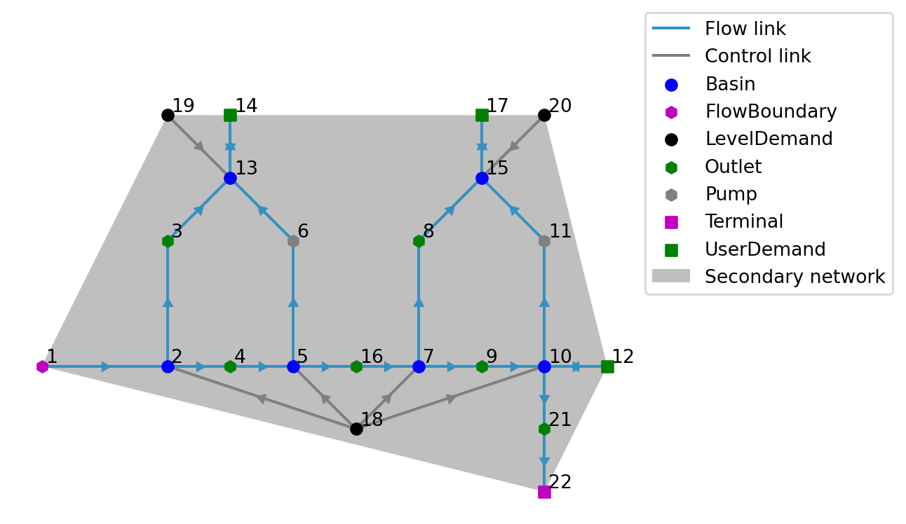
Set up a minimal model with a Junction that divides the flow for an equation test.
The inflow of Junction #4 comes from a TabulatedRatingCurve, a FlowBoundary and a PID controlled Pump, so the Junction flows depend on the Basin storages and on the PID integral. UserDemand #5 takes precedence over the division of the remainder over Basin #9 and Terminal #6, so that the Junction flows change the storage of a Basin.
39 junction_flow_boundary
Create a model with a FlowBoundary time series flowing through a Junction into a Basin.
The Junction has a row in Junction / static, so it stays in the simulation. The flow rate alternates daily between 0 and 1e-2 m³/s with block interpolation, so the flow that enters the Junction jumps at every day.
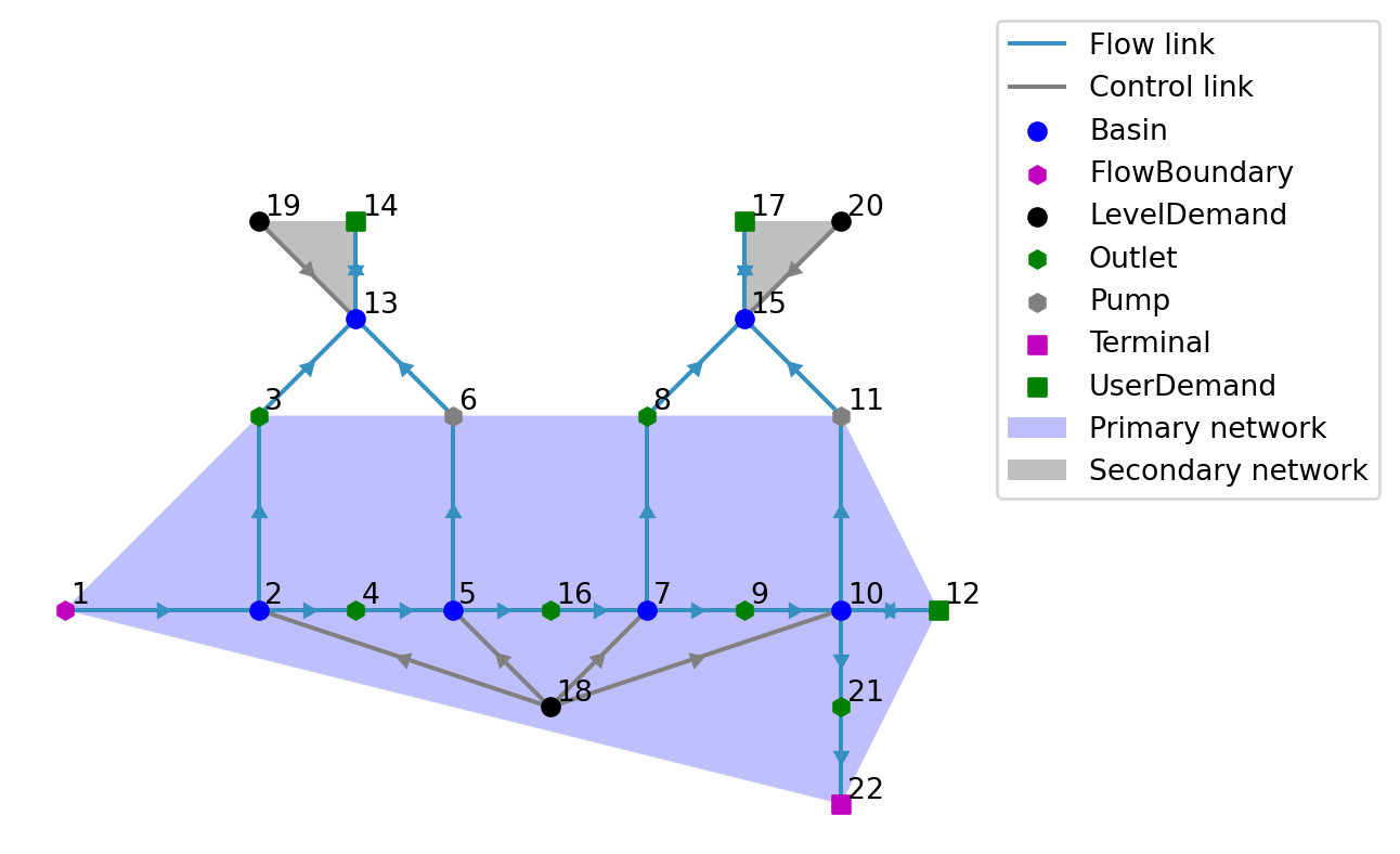
40 junction_fraction
Create a connected model with Junction nodes that divide the flow and supply UserDemand nodes.
These Junction nodes have rows in Junction / static, so they stay in the simulation instead of being removed from the network. From upstream to downstream it contains:
- A FlowBoundary whose flow Junction #22 divides over two Basins.
- A Pump whose flow Junction #23 divides over Junction #6, which supplies UserDemand #8 and passes the remainder on, and Junction #25, where that remainder joins the other part (a confluence) before flowing into Basin #11.
- A UserDemand whose return flow Junction #24 divides over Basin #11 and Junction #10, which supplies UserDemand #12 with less than its demand and passes the remainder on to Basin #13.
- A Pump whose flow Junction #15 divides over two Terminals, after UserDemand #16 took its demand.
Tracers are enabled, so the flows through all these configurations also carry tracer mass.
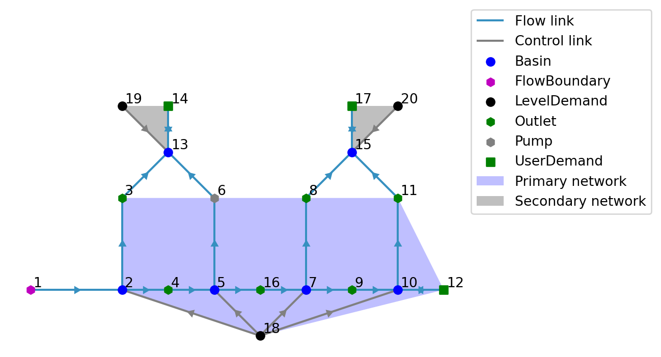
41 junction_into_junction
Create a model where a Junction with fractions flows into Junctions without rows.
FlowBoundary #1 flows into Junction #2, which sends 40% to Junction #4 and the rest to Junction #5, neither of which has rows. Junction #4 also receives FlowBoundary #3 and passes everything on to Basin #6. Junction #5 connects Basin #7 with LinearResistance #8, which drains into LevelBoundary #9, so it is a Junction group with one Basin. The rows of Junction #2 name #4 and #5, and apply to the links that replace them. The Junction / static table is written to NetCDF rather than the database.
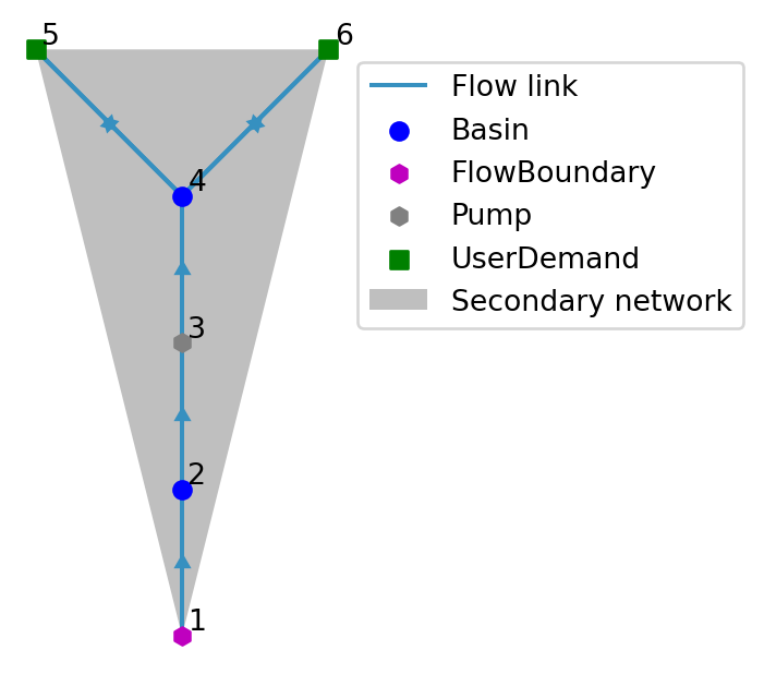
42 junction_level
Create a model that shows which downstream level a structure feeding a Junction sees.
Two identical Outlets with a max_downstream_level of 1.5 m drain Basin #1. Outlet #2 flows via Junction #3 into Basin #4 alone, so it sees the level of Basin #4 (2 m) and is drowned, whether or not Junction #3 has a row in Junction / static. Outlet #5 flows via Junction #6, which divides the flow over Basins #7 and #8 (also 2 m), so it has free outflow and keeps flowing.
43 junction_no_basin_allocation
Create a model without Basins with allocation: the chain of junction_no_basin_model.
Allocation gives the boundary flow to the downstream UserDemand #6, which has the higher demand priority.
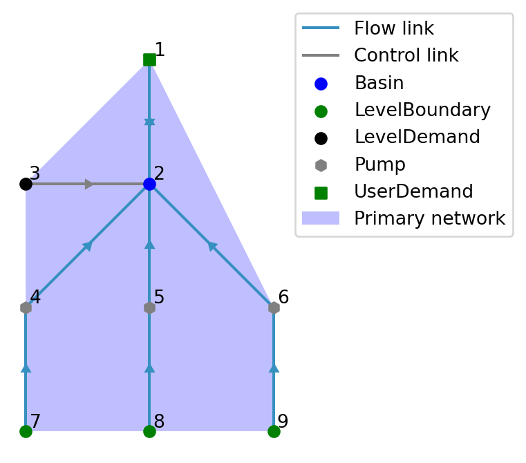
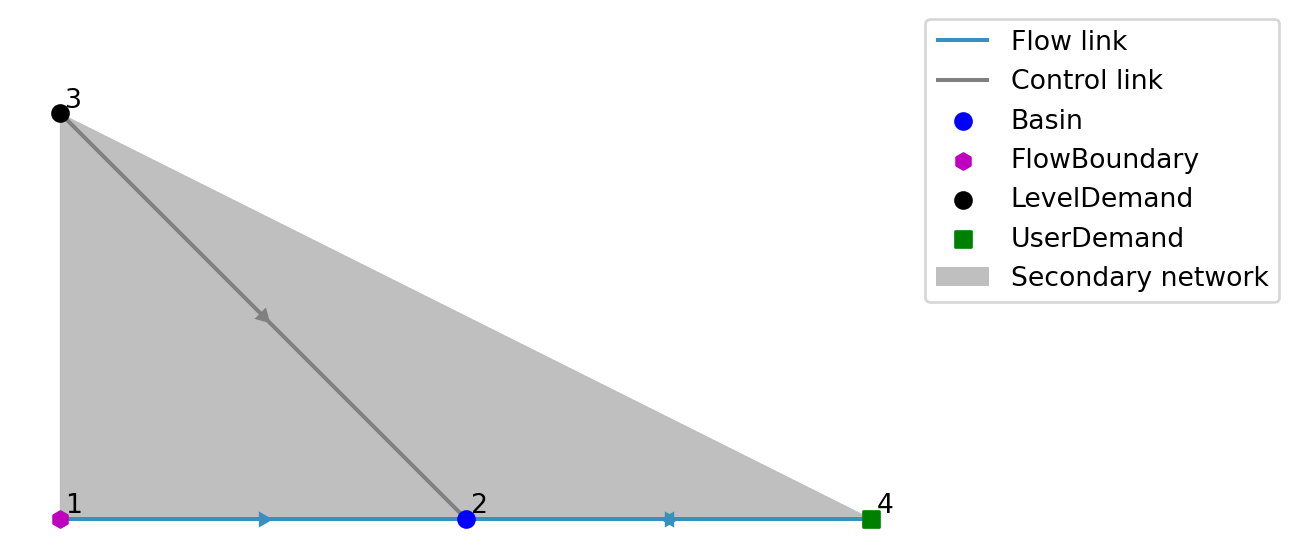
44 junction_no_basin
Create a model without Basins: a chain of Junction and UserDemand nodes.
Without allocation the upstream UserDemand #3 is served first, regardless of its lower demand priority.
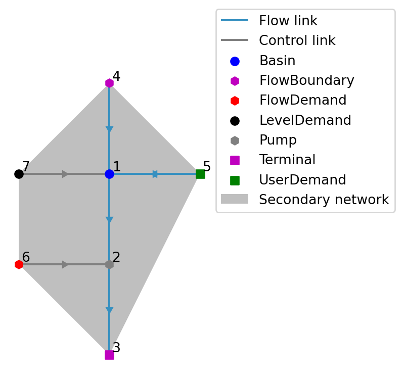
45 junction_pid
Create a model with a PID controlled Basin that is fed via a Junction that stays in the simulation.
The derivative term of the PID control depends on the inflow of the Basin, which comes from the FlowBoundary via the Junction.
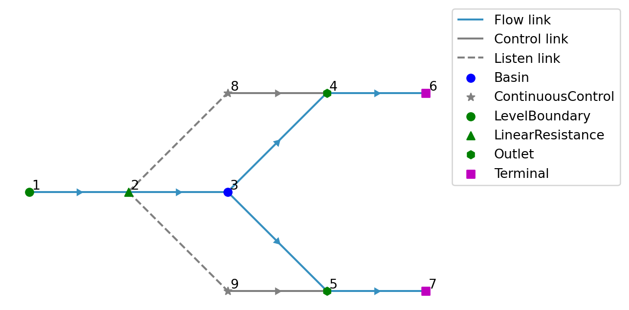
46 junction_shortage_tracer
Create a model with a substance that reaches a Junction node after a UserDemand takes all water from it.
This is junction_continuous_control_model with tracers, in which UserDemand #4 returns nothing to Basin #6. FlowBoundary #20 brings the substance Pulse into Basin #1 from 2020-01-20, after the flow of TabulatedRatingCurve #2 dropped below the demand. Within the solver tolerance the flow from Junction #5 into Basin #6 is then negative, which is water from Basin #6 that does not have Pulse.
47 junction_tracer
Create a model for testing the tracers through a Junction that supplies a UserDemand.
Two FlowBoundaries flow into Junction #3, of which only #1 has a concentration for the substance Foo. UserDemand #4 abstracts from Junction #3 and returns to Basin #6, while the remaining flow goes to Basin #7.
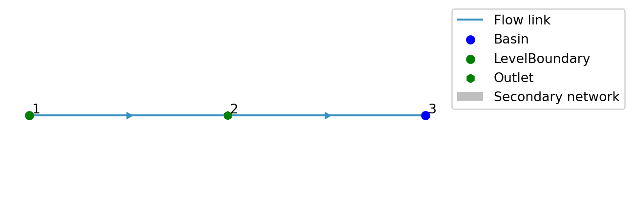
48 leaky_bucket
Bucket model with dynamic forcing with missings at Deltares’ headquarter. 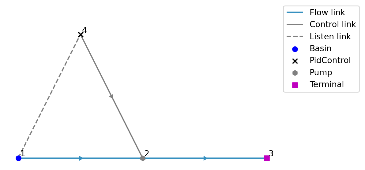
49 level_boundary_condition
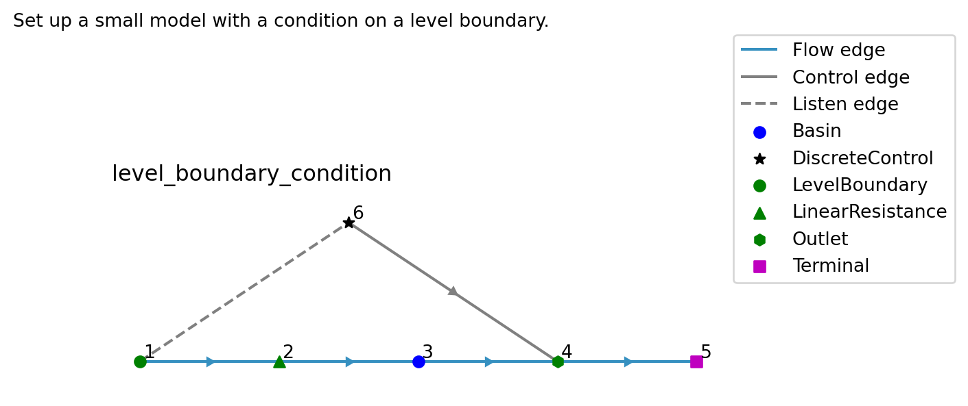
Set up a small model with a condition on a level boundary. 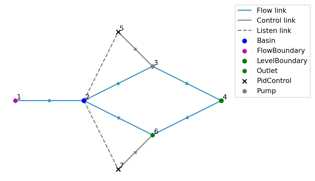
50 level_demand
Small model with LevelDemand nodes. 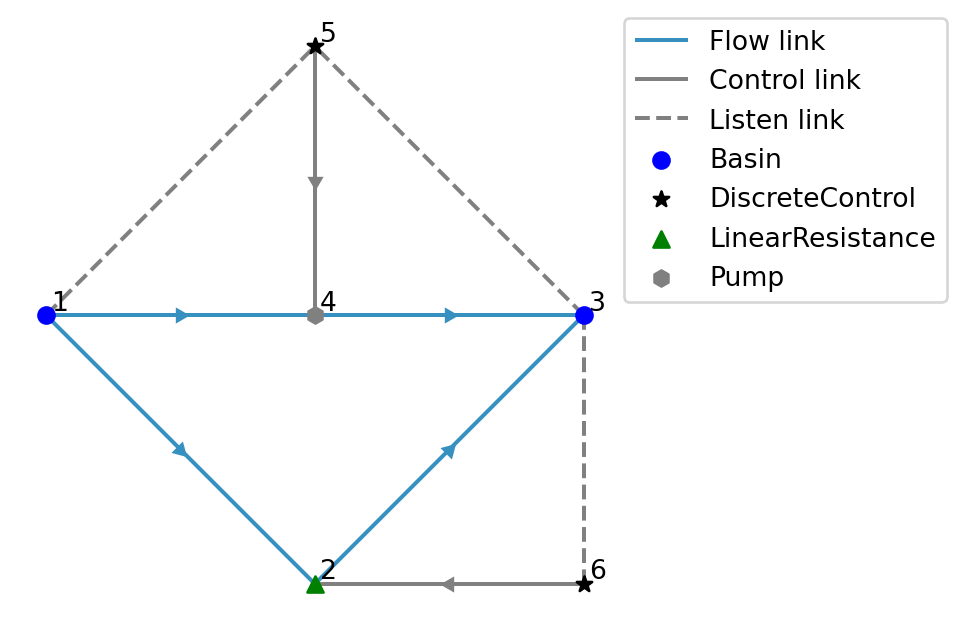
51 level_demand_with_rating_curve
Create a model with a Basin that has a LevelDemand and an allocation-controlled TabulatedRatingCurve draining to a Terminal. 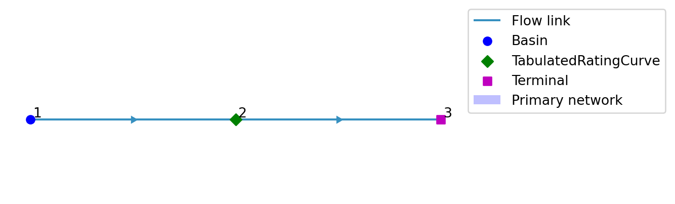
52 level_range
Keep the level of a Basin within a range around a setpoint, under the influence of time-varying forcing.
This is done by bringing the level back to the setpoint once the level goes beyond this range.

53 linear_resistance_demand
Small model with a FlowDemand for a node with a max flow rate. 
54 linear_resistance_demand_negative_flow
Small model with a FlowDemand for a node that has a negative physical flow. 
55 linear_resistance
Set up a minimal model which uses a linear_resistance node. 
56 local_pidcontrolled_cascade
Demonstrating model for the cascade polder project from our partner. 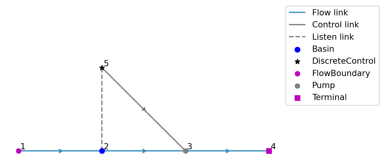
57 manning_resistance_control
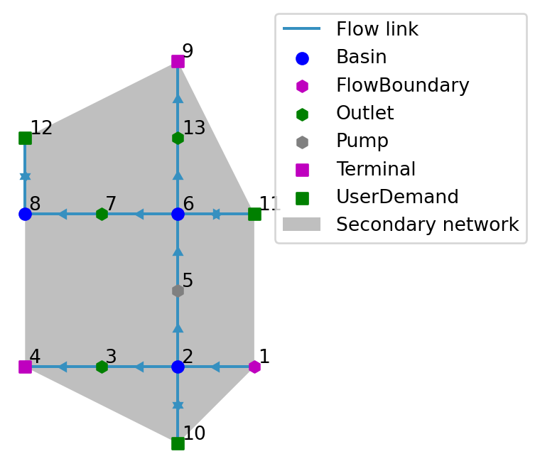
Discrete control on a ManningResistance.
Basin 1 drains over a ManningResistance into Basin 3. The Control node makes the ManningResistance (almost) closed by increasing the roughness once the level of Basin 1 drops below a threshold.
58 manning_resistance_deep_basin
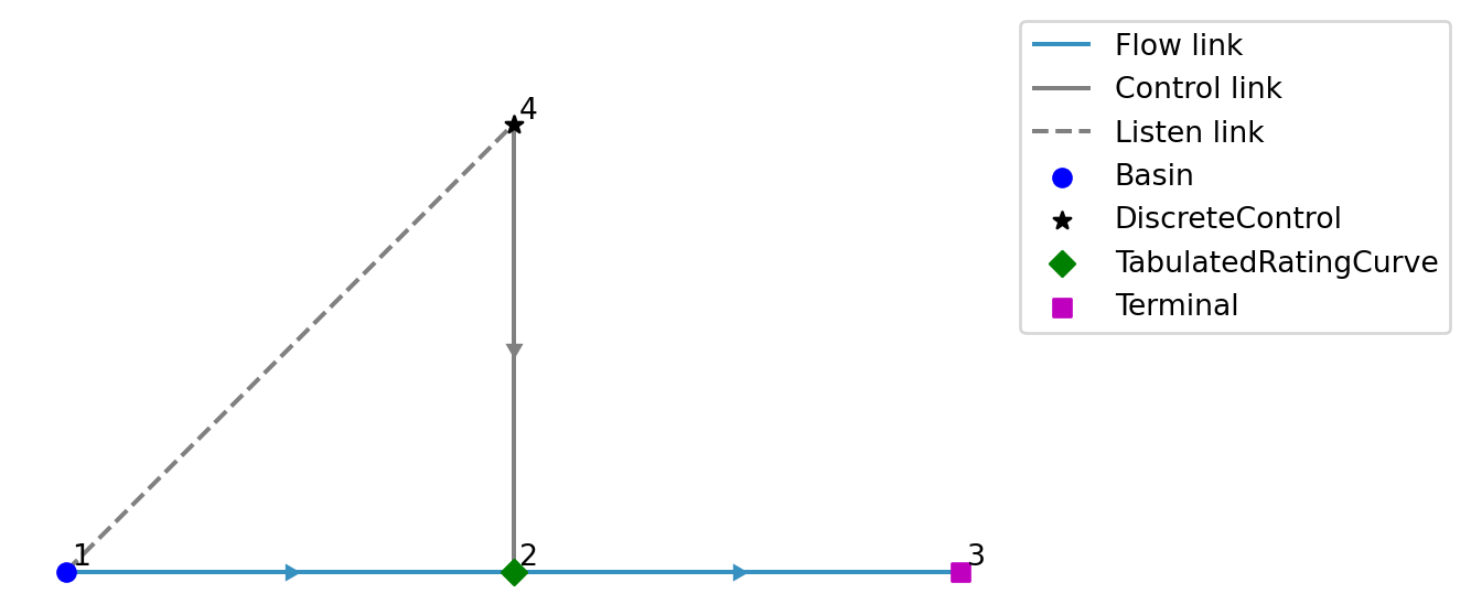
Set up two Basins at equal levels joined by a ManningResistance, one profile far below the sill.
The Manning flow is then large for a tiny level difference, and the flow through the node changes direction every few hours. Taken from the national LHM model, where capping such a flow by a critical flow that does not vanish at equal levels made the flow jump between plus and minus the critical flow and stalled the solver.
59 manning_resistance
Set up a minimal model which uses a manning_resistance node. 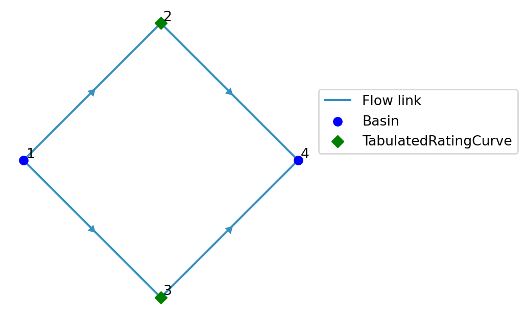
60 medium_primary_secondary_network

61 medium_primary_secondary_network_verification
62 minimal_subnetwork
Create a subnetwork that is minimal with non-trivial allocation. 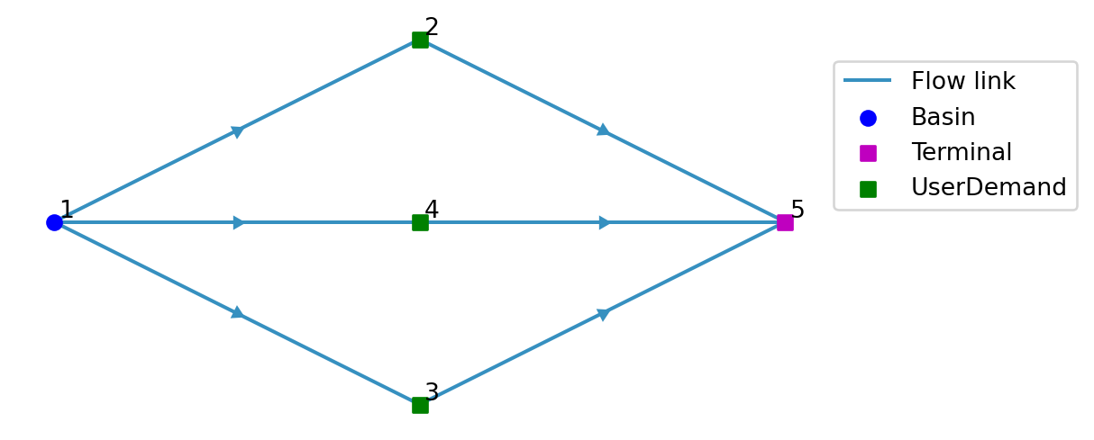
63 misc_nodes
Set up a minimal model using flow_boundary and pump nodes. 
64 multi_level_demand
Create a model that has a level demand with multiple priorities. 
65 multi_priority_flow_demand
Set up a model which contains a FlowDemand node with multiple demand priorities. 
66 multiple_route_priorities
Set up a model to test route prioritization. 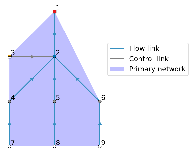
67 observation
Model with three Observation nodes, one of which is unlinked. 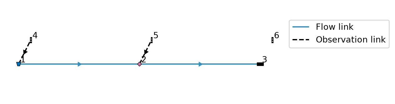
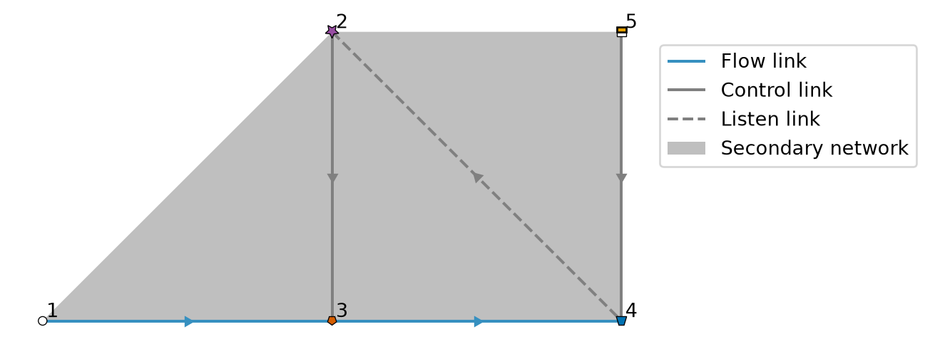
68 outlet_allocation_discrete_control
LevelBoundary supplies water via an allocation-controlled Outlet to a Basin with a LevelDemand.
DiscreteControl switches at basin level 0.5: - Below 0.5: allocation-controlled (allocation decides flow) - Above 0.5: prescribed flow
Topology: level_boundary –> outlet –> basin <– level_demand ^ | | v discrete_control
69 outlet_continuous_control
Set up a small model that distributes flow over 2 branches. 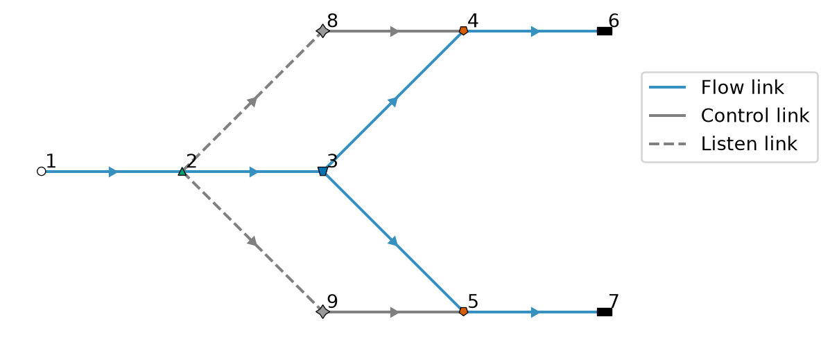
70 outlet
Set up a basic model with an outlet that encounters various physical constraints. 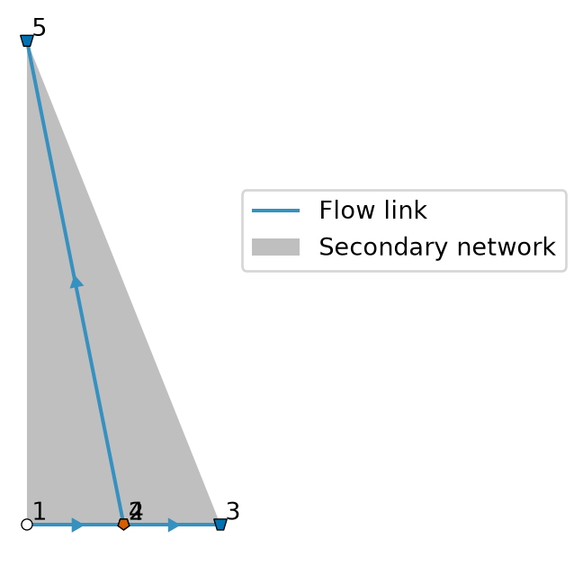
71 pid_control_equation
Set up a model with pid control for an analytical solution test. 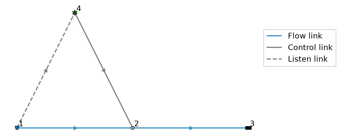
72 pid_control
Set up a basic model with a PID controlled pump controlling a basin with abundant inflow. 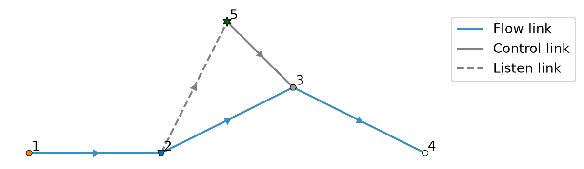
73 polder_management
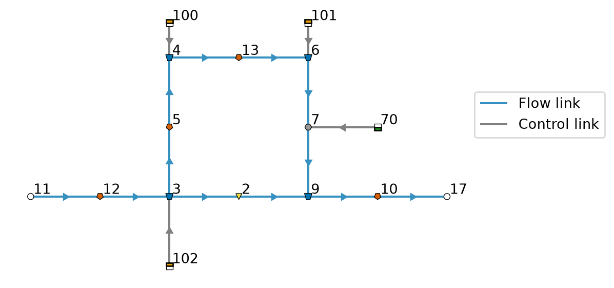
Set up a model where the water level in the boezem is be higher than in the polder system.
To maintain the target water levels in dry periods in the polder system, a water supply of 2 m³/s is required during two periods of the year: day 90 to 180 and day 270 to 366. Flushing is included as well: 1.5 m³/s during day 90 to 180.
74 precompile_workload_allocation
Model that runs in the precompile workload of Ribasim, with allocation.
Like precompile_workload_model, but it combines test models with all demand node types in allocation subnetworks.
75 precompile_workload
Model that runs in the precompile workload of Ribasim, without allocation.
Code that is compiled while running this model is cached, and reused for other models. Therefore it combines many test models as separate parts of one network, to cover all node types and input tables, with the default solver and interpolation settings.
76 pump_discrete_control
Set up a basic model with a Pump controlled based on Basin levels.
The LinearResistance is deactivated when the levels are almost equal.
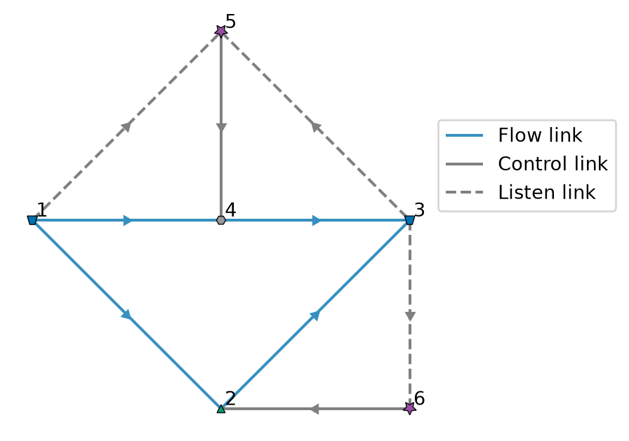
77 pump_pit
Set up a small pump pit between two boezem Basins, after Boezemgemaal Halfweg in the LHM model.
The pit of 119 m² is joined to both Basins by short ManningResistance nodes, whose flow goes with the square root of the level difference. When the pump stops the pit fills up to about 0.2 mm below the Basins, where it is very stiff. At the same time, Outlets in tiny Basins open, which keeps the time step small while the pit fills.
With a Newton iteration that is accepted after a single iteration on a convergence rate measured long before, for a different iteration matrix, the pit starts to oscillate by a few millimetres every time step instead of settling. Thousands of LinearResistance nodes with a constant flow dilute the RMS norm of the error estimate, as the many states of a large model do, so the oscillating states keep the error estimate just above the band where the time step can grow. That made the coupled LHM model crawl for hours with time steps of 0.2 s.
78 rating_curve_between_basins
Set up a minimal model which uses a tabulated_rating_curve node. 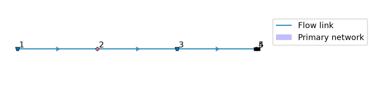
79 rating_curve
Set up a minimal model which uses a tabulated_rating_curve node. 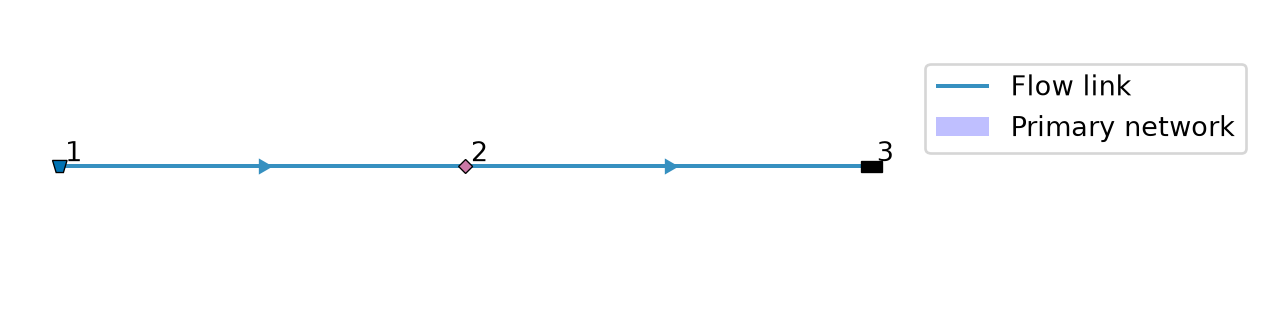
80 small_primary_secondary_network
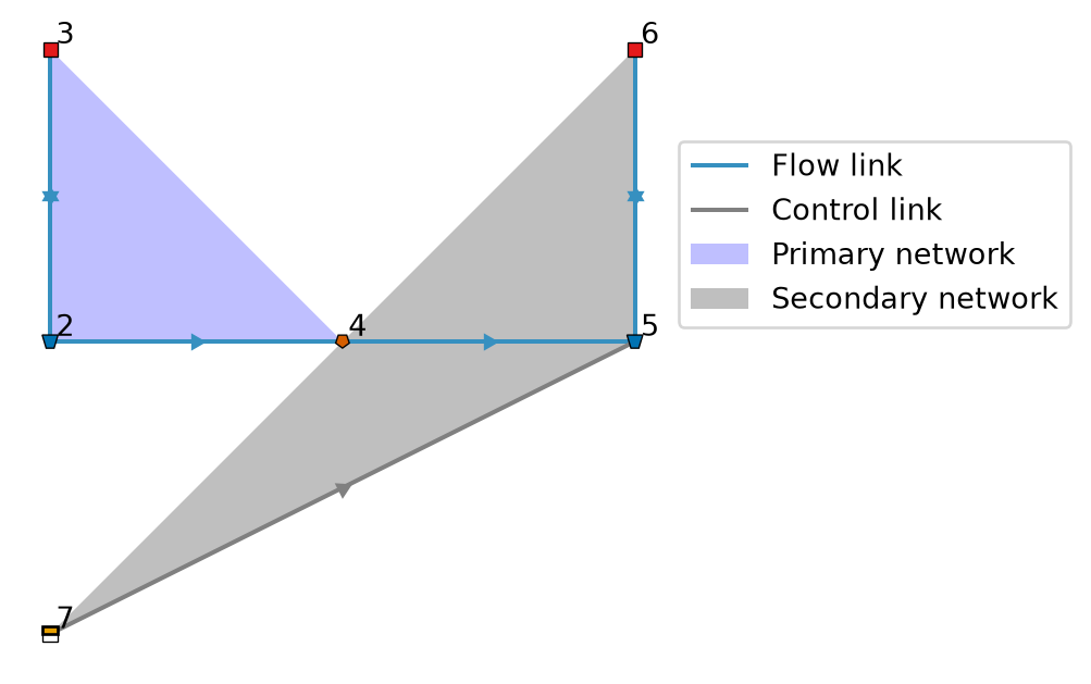
81 small_primary_secondary_network_verification
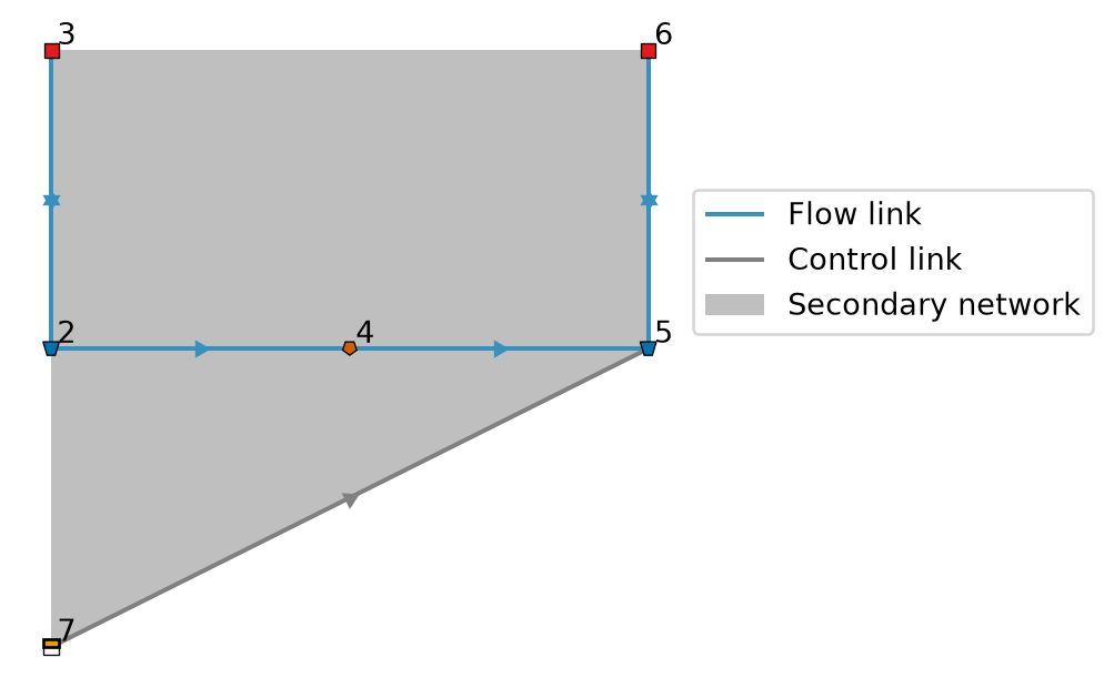
82 storage_condition
Create a model with a discrete control condition based on the storage of a Basin. 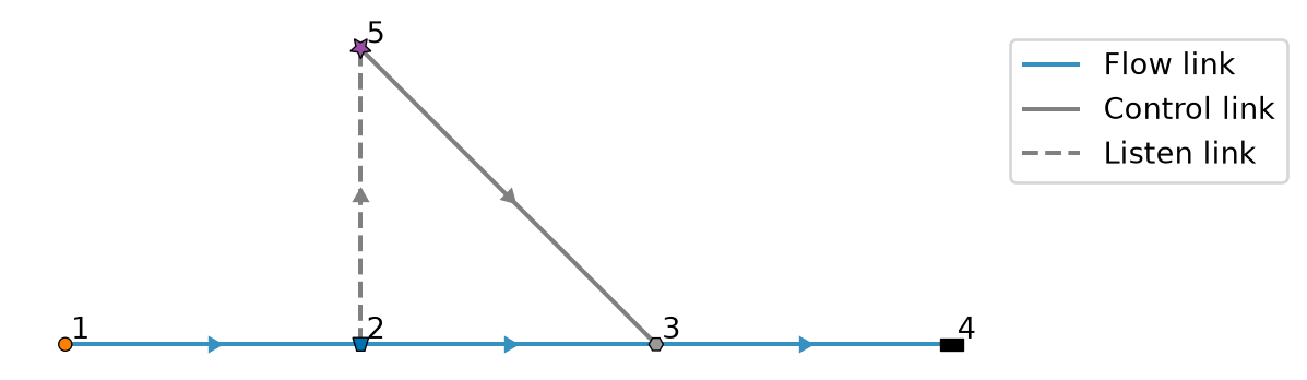
83 switch_allocation_control
Create a model that switches allocation control on and off based on a DiscreteControl node. 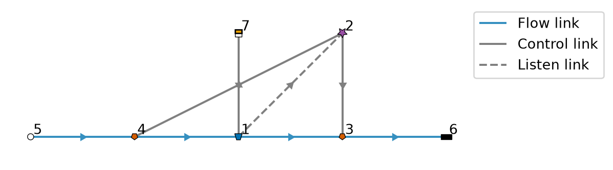
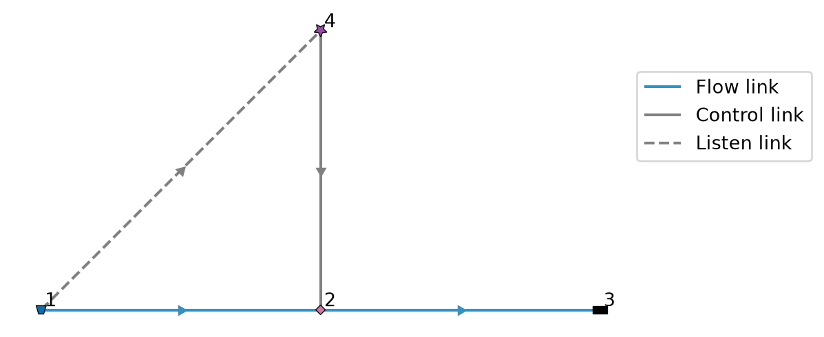
84 tabulated_rating_curve_control
Discrete control on a TabulatedRatingCurve.
The Basin drains over a TabulatedRatingCurve into a Terminal. The Control node will effectively increase the crest level to prevent further drainage at some threshold level.
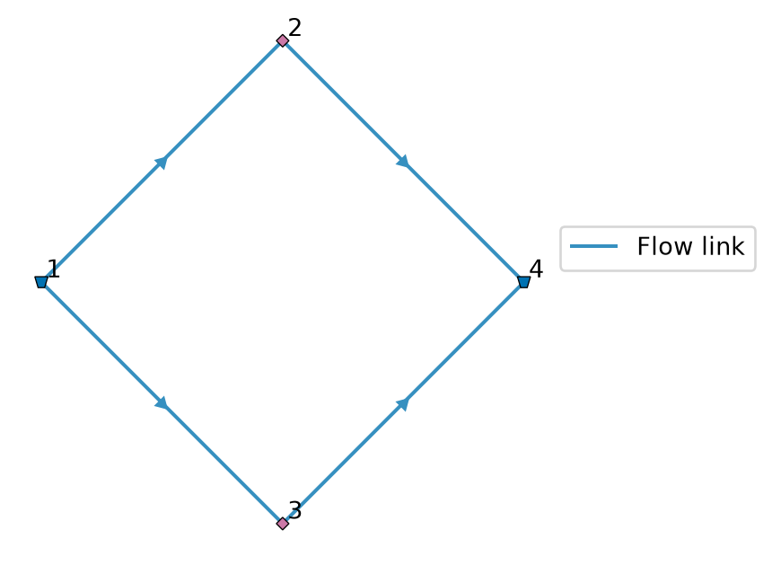
85 tabulated_rating_curve
Set up a model where the upstream Basin has two TabulatedRatingCurve attached.
They both flow to the same downstream Basin, but one has a static rating curve, and the other one a time-varying rating curve. Only the upstream Basin receives a (constant) precipitation.
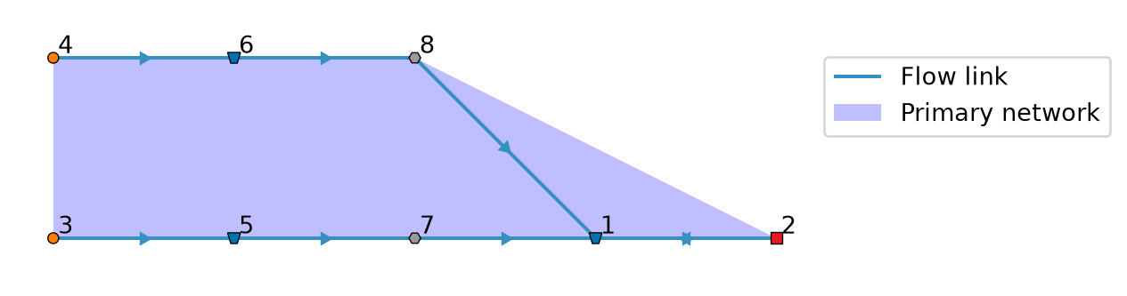
86 tied_routes
Set up a model where two reservoirs supply a UserDemand over Pumps with the same route priority.
How the supply is divided over the Pumps makes no difference for the objectives, so allocation should stay close to the division of the previous timestep.
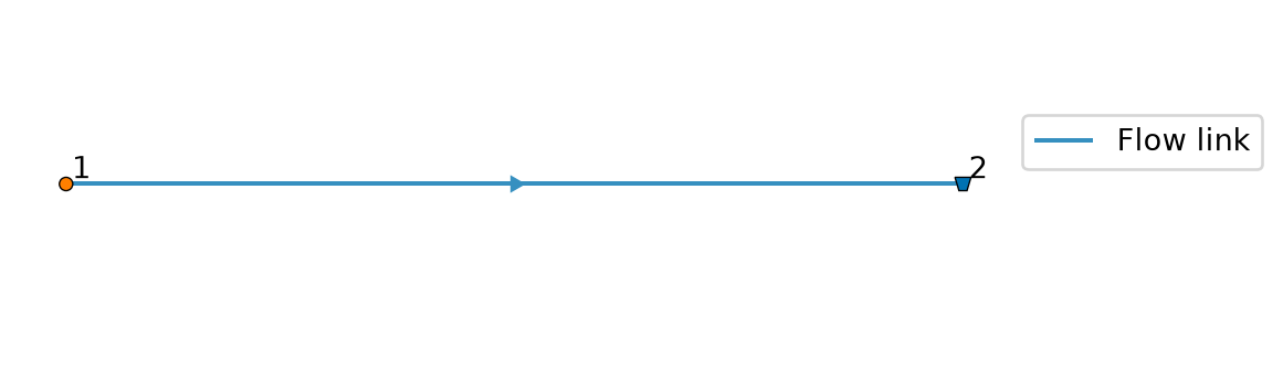
87 tracer_boundary_pulse
Set up a Basin without outflow that gets a pulse of a substance from a FlowBoundary.
The times at which the concentration changes are not used by anything else in the model. All mass in the pulse stays in the Basin, which is the flow rate times the pulse duration.
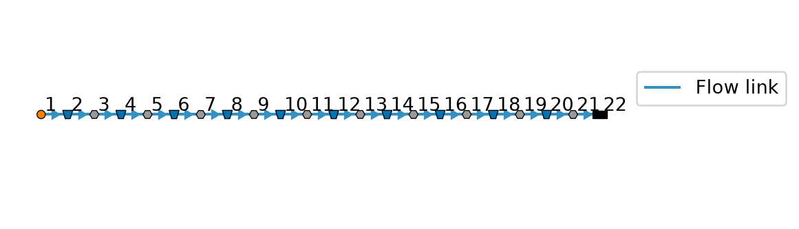
88 tracer_chain
Set up 10 equal Basins in series with a constant flow, to compare the tracers to the analytical solution.
Each Basin holds 1000 m³ and the flow is 1 m³/s, so the residence time per Basin is 1000 s. The FlowBoundary tracer in the last Basin follows the tanks in series solution.
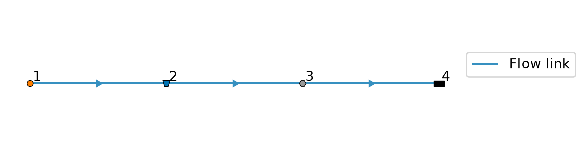
89 tracer_evaporation
Set up a Basin with a constant throughflow and evaporation that leaves the mass behind.
Evaporation concentrates the substances, the FlowBoundary tracer rises above 1. The storage decreases linearly, for which the concentrations have an analytical solution.
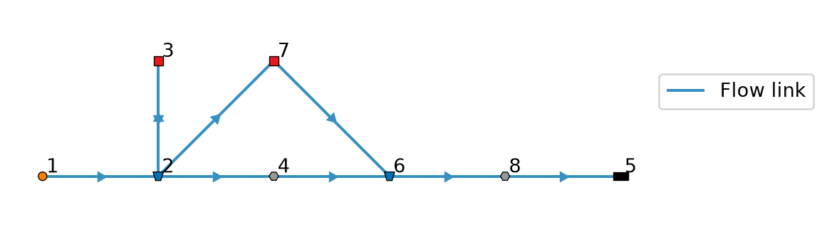
90 tracer_user_demand
Set up UserDemands that return half of their abstraction.
One returns to the Basin it abstracts from, the other to a downstream Basin. The return flows should carry the concentrations of the abstracted water.
91 transient_condition
DiscreteControl based on transient condition. 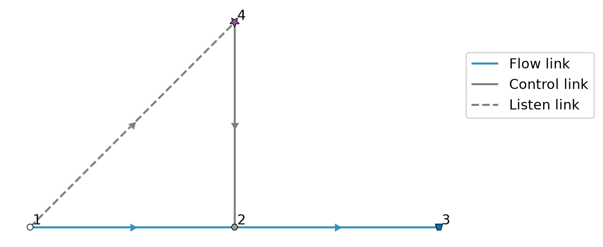
92 transient_pump_outlet
Set up a model with time dependent pump and outlet flows. 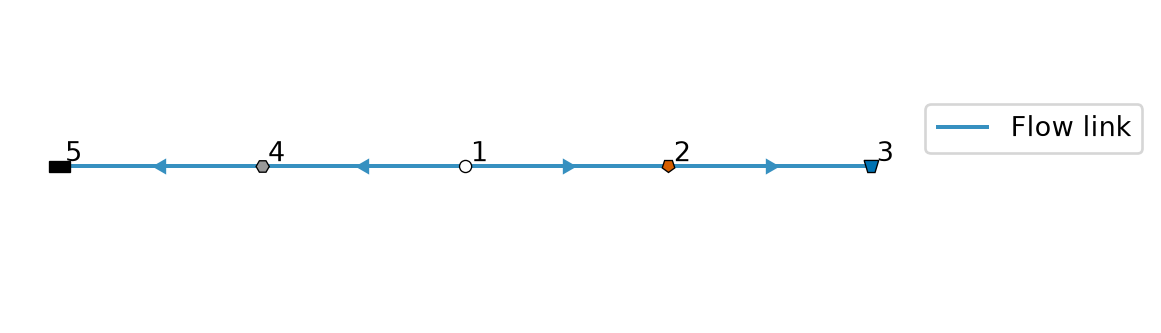
93 trivial
Trivial model with just a basin, tabulated rating curve and terminal node. 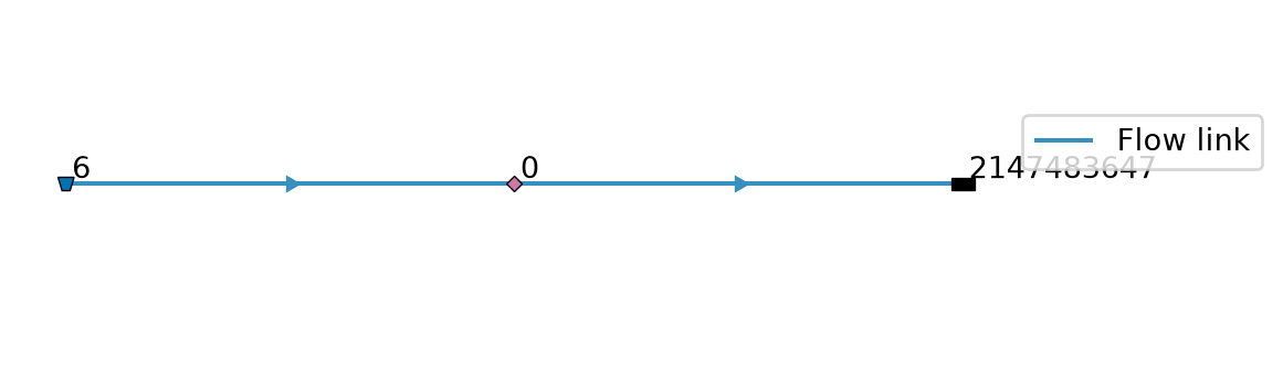
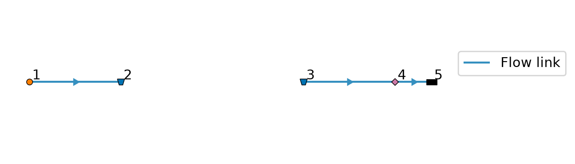
94 two_basin
Create a model of two basins.
The basins are not connected; the model is mostly designed to test in combination with a groundwater model.
The left basin receives water. In case of a coupled run, the water infiltrates in the left basin, and exfiltrates in the right basin. The right basin fills up and discharges over the rating curve.
95 two_basin_user_demand
Two Basins supplying a single UserDemand, exercising multi-inflow with route priority.
Topology (issues #2725/#2776): FlowBoundary 1 (1 → 0 over time) → Basin 3 (route_priority=1, preferred) ─┐ ├─→ UserDemand 5 → Terminal 6 FlowBoundary 2 (constant 2) → Basin 4 (route_priority=2) ─┤ └─→ Outlet 7 → Terminal 8 LevelDemand 9 ─→ Basin 4 (target level 1 m)
With allocation on, the UserDemand (demand = 2) initially draws 1 from each basin. As FlowBoundary 1’s supply decays toward zero, Basin 3 can no longer keep up; the LP shifts the deficit onto Basin 4 (the higher-priority-number fallback) so total UD inflow stays at 2. The allocation-controlled outlet from Basin 4 plus a LevelDemand hold Basin 4’s level at 1 m, letting the excess supply from FlowBoundary 2 drain to Terminal 8 when the UD does not need it.
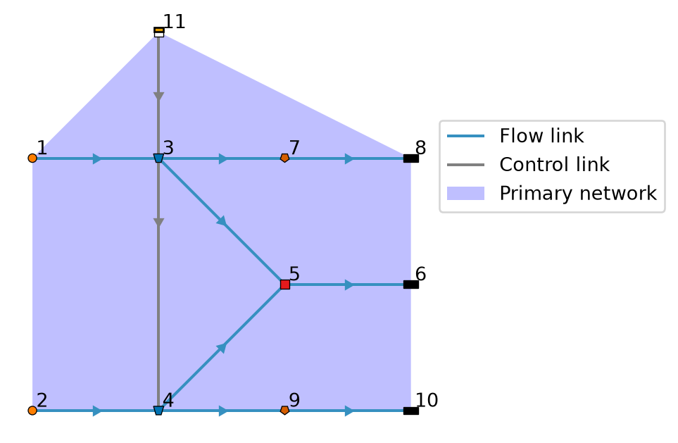
96 user_demand
Create a UserDemand test model with static and dynamic UserDemand on the same basin.